Important Notice
This document provides general technical guidance for electric cooktop installation.
Before proceeding with installation, you must:
- Verify and strictly adhere to the Manufacturer’s Installation Manual specific to your model.
- Comply with all local, provincial, and federal regulations, including the Canadian Electrical Code (CEC), concerning circuit sizing, wiring methods, grounding/bonding requirements, and minimum clearances to combustible materials.
- If you are not comfortable performing the electrical connection, consult a Licensed Canadian Electrician to ensure compliance with the CEC.
Failure to comply with manufacturer instructions and applicable Canadian codes may result in fire, injury, property damage, and the voiding of your warranty and insurance coverage.
An electric cooktop is simple to live with and precise when installed correctly. The work is mostly planning and careful setup: confirm a dedicated circuit, size the cut-out to the template, support the countertop so it stays flat, and make the electrical connection with proper bonding and strain relief. The steps below cover radiant and induction models and focus on safe clearances, clean wiring, and checks you can repeat later.
Plan The Space And Electrical Supply
Start with access, safety, and power. Map the path from entry to the kitchen and protect floors with non-slip runners. Clear drawers around the cut-out so the chassis can be lowered without snags. Confirm a junction box is reachable below the cooktop and that the branch circuit is dedicated to this appliance. Most electric cooktops require a 240 V, 60 Hz supply on a two-pole breaker sized to the nameplate amperage. Conductor gauge must match both the current and the run length. If the existing cable uses aluminium conductors, use AL/CU-rated connectors and antioxidant compound, or have the run replaced. Do not oversize a breaker without matching conductors, and do not undersize it to be cautious; both choices add risk and may void coverage.
A quick survey prevents interference. Check that nearby drawers, the oven below, or side panels will not obstruct cooling slots or press on the flexible conduit. If a range hood is present, verify the cooktop’s clearance to overhead cabinets and the hood manufacturer’s minimums so hot air can rise without scorching finishes. Where the countertop material is heat-sensitive, confirm the edging or foil tape specified in the model manual before any cutting.
Essential Tools and Materials for Cooktop Installation
- Tape measure, square, spirit level, pencils, jigsaw with a fine blade, clamps, and off-cut supports.
- Wire strippers, side cutters, torque screwdriver or wrench for lugs, listed wire connectors rated for temperature and conductor type, and a listed strain-relief for the whip.
- Non-compressible shims, soft pads to protect glass, a junction box with cover, and an edge guard or grommet where the conduit passes through a panel.
Circuit sizing at a glance
| Breaker (A) | Typical input (kW) | Minimum copper gauge (AWG)* | Notes |
|---|---|---|---|
| 30 | 5.7–7.2 | 10 | Common for smaller radiant units. |
| 40 | 7.2–8.8 | 8 | Frequent on mid-size radiant and some induction. |
| 50 | 8.8–11.5 | 6 | Larger induction or multi-zone radiant. |
| 60 | 11.5–14 | 6 or 4 (per manual) | Only where specified by the model. |
*Always follow the installation manual and local rules for conductor type, temperature rating, and run length.
Connecting Cooktop to Junction Box
Open the junction box and identify conductors: two hots (often red and black), neutral if required by your model, and an equipment bonding conductor (green or bare). The box should be metal or a listed high-temperature polymer with an intact cable clamp and cover. If the box sits where the cooktop chassis will press against it, relocate it slightly lower or further back so the appliance can sit flush without crushing the whip.
De-energise the breaker and prove it with a meter or a proven non-contact tester. Inspect the flexible conduit from the cooktop for kinks, sharp bends, or damaged armour. Confirm the whip length reaches the box without tension; a gentle sweep prevents stress on lugs and strands. Where the conduit passes through a cabinet wall, fit a bushing or grommet to protect jackets from a cut edge.
Junction box readiness
| Item | Target | Reason |
|---|---|---|
| Box type | Listed metal or heat-rated polymer with cover | Withstands elevated temperatures under benches. |
| Cable entry | Clamp grips outer jacket, not individual conductors | Preserves insulation and strain relief. |
| Conductor ID | Two hots, neutral if required, equipment bond | Correct mapping and safe return paths. |
| Clearance | Box not in contact with chassis | Prevents rattles and abrasion. |
Plan the conduit path before you lower the glass. Keep the whip away from drawer slides and away from sharp cabinet edges. Avoid routing across hot oven panels below. If a protective edge is needed, apply an edge guard now. Place soft pads on the counter to protect the glass when dry-fitting.
How to Measure and Ensure Cooktop Clearance
Measure the countertop opening at the front and back. Countertops are rarely perfectly parallel; even a few millimetres of taper can pinch the chassis or distort the frame. Compare all dimensions to the cut-out diagram in your model’s instructions. Allow for trim overlap and any specified air gap between the cut-out edge and the cooktop body. If the manual calls for heat-resistant edging or foil tape along the cut-out edge, install it now.
Mind the material. Stone, solid surface, laminate, and wood each have rules for minimum edge distances and reinforcement near heat sources. Avoid unsupported spans; wide, thin countertops can bow under clamping force. Where the opening removes too much structure, add cross-rails or support cleats so the glass sits flat and does not rock.
Cutout and support targets
| Parameter | Typical range | Practical notes |
|---|---|---|
| Side clearance to combustibles | Per manual (often 6–13 mm / ¼–½ in) | Preserves airflow and trim fit. |
| Rear clearance to wall | Per manual (often ≥ 50 mm / 2 in) | Prevents heat soak and pinch points. |
| Overhead clearance | Per hood and cabinet specs | Keeps rising heat away from finishes. |
| Flatness across cutout | ≤ 1 mm rock across diagonals | Avoids glass twist and stress cracks. |
Dry-Fit And Seal Correctly
Set the cooktop into the opening without wiring to check trim coverage, corner clearance, and conduit routing. Lift it back out to install the gasket the manufacturer supplies. Some models require a bead of heat-resistant sealant; others rely on a pre-applied foam or rubber gasket. Over-sealing traps spills and complicates service, so follow the manual closely.
Set The Cooktop And Level The Support

Lower the unit into the opening with soft pads in place. Use a spirit level across the glass from side to side and front to back. If the countertop is not perfectly flat, place non-compressible shims beneath landing tabs or under support rails until the glass sits level and without rock. Tighten clamp brackets evenly, alternating sides so the frame seats without distortion. Screws must be the specified length; over-long screws can pierce the chassis or snag wiring. As clamps draw down, watch the glass: it should settle uniformly with no corner sitting proud.
A short heating step helps confirm seating. After wiring is complete and power restored, run a low setting on one element for a few minutes while touching the counter near each corner. Warm is normal; a hot spot suggests a clamp distorted the frame or blocked a cooling slot. Correct clamp tension and recheck.
Safety Checks Before Energising
Confirm that no copper is exposed beyond connector skirts, the clamp grips the cable jacket, and the bonding path is intact. Tug each conductor gently to verify seating. Close the junction box with its cover; exposed splices are a failure point and a safety risk. Update the panel directory with the appliance description and breaker size for clarity during future work.
Make The Electrical Connection And Commission
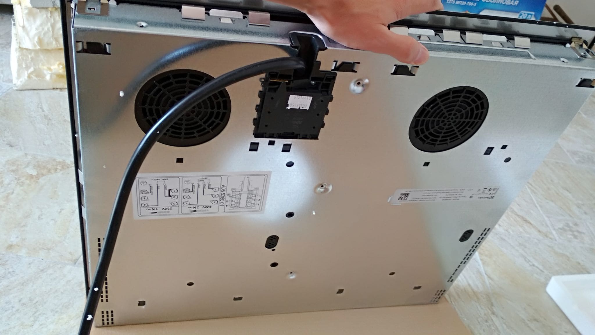
Review the wiring diagram on the cooktop label. Radiant and induction models often differ in neutral requirements: some operate on two hots plus bond, others require a neutral for electronics or auxiliary features. Feed the whip into the junction box and secure it with a listed connector. Strip conductors to the length the connector maker specifies. Join colour to colour per the diagram: hot to hot, neutral if used, and bond to the equipment grounding conductor (and to a metal box if present). Tighten set-screw lugs to the stated torque; loose lugs heat under load, over-torqued lugs damage strands.
Restore power at the breaker. The control panel should wake. Induction models may self-test briefly; radiant models usually show a ready indicator. Start with a low setting on one element and step up in stages. Cabinet faces near the cut-out should feel warm, not hot, after several minutes.
Cooktop Performance Test
| Check | Method | Acceptance range |
|---|---|---|
| Boil time baseline | 1 L water in a flat pan, room-temp water | Induction: about 3–5 min; Radiant: about 6–9 min (varies by element size and power). |
| Simmer control | Reduce to a stable simmer after boil | Setting holds without wild pulsing or clicks. |
| Residual-heat indicator | Observe H indicator after shut-off | Remains on until surface cools below a safe threshold (commonly near 60 °C). |
| Zone mapping | Engage bridge or dual-zone with matching cookware | Activation indicators match the heated area felt through the glass. |
Troubleshooting Snapshot
- Element does not heat: verify breaker position, conductor joins, and that control lock is off. For induction, confirm cookware attracts a magnet and sits flat.
- Odour on first use: a brief smell is normal as oils burn off. Ventilate and run elements at medium for several minutes.
- Hot cabinet faces: recheck clearances, clamp tension, and that cooling slots are not blocked by trim or sealant.
Tools and materials list
- See “Gather Tools And Materials.” Keep a torque driver handy; most lugs specify a value, and correct torque prevents hot joints. Ensure spare listed connectors are available in case a splice must be remade.
Cooktop Installation Final Verification
- Cut-out matches the template; glass sits flat; gasket compressed evenly without squeeze-out into cooling slots.
- Junction box accessible; conductors joined per the diagram; lugs torqued; cover installed; panel directory updated.
- Elements heat evenly; induction recognises compatible cookware; residual-heat indicators operate; no unusual noises at high power.
The target is stable, even heat without stressing cabinets or wiring. You achieve it by planning the cut-out, protecting the countertop, routing the conduit with a smooth bend radius, making a clean electrical connection with proper bonding, and running repeatable performance checks on day one. Keep notes—breaker size, conductor gauge, and boil times—so future service is faster and more precise.
FAQ
What breaker size and wire gauge should I use?
Match the cooktop’s nameplate current and the installation manual. As a rule: 30–60 A breakers with copper conductors sized per the manual and the Canadian Electrical Code (CEC).
Is a neutral required for induction models?
Some are 2-hot + equipment bond only, others need a neutral for controls. Follow the wiring diagram on the product label.
Can I reuse aluminium branch wiring?
Only with devices and connectors rated AL/CU plus antioxidant; otherwise replace with copper. Mixing without proper terminations is unsafe and non-compliant.
What clearances should I keep?
Follow the cooktop manual and the range hood’s manual. Typical values: side 6–13 mm, rear ≥50 mm, and hood height per the hood specification.
Can I install above a wall oven?
Often yes, if both manuals allow it and ventilation paths are not blocked. Verify cabinet cut-out strength and junction-box placement.
How do I prepare the cut-out?
Use the supplied template. Keep edges smooth, reinforce weak spans, and ensure flatness so the glass does not rock. Apply heat-resistant edging if the manual specifies it.
How do I verify a safe connection?
De-energise, strip to spec, torque lugs to the stated value, and confirm the bonding path. Close the junction box with its cover before energising.
Sources
- Manufacturer installation guides for your specific model (e.g., Bosch, GE, Whirlpool, Frigidaire, Samsung).
- CSA C22.1, Canadian Electrical Code, Part I (current edition).
- Provincial electrical safety authorities for local requirements and permits: Electrical Safety Authority (Ontario), Technical Safety BC, Alberta Municipal Affairs, and equivalents.
- CAN/CSA product standards applicable to household cooking appliances and wire/connectors as referenced by the CEC.