An electric wall oven rewards methodical preparation. Good installation keeps surrounding cabinetry within safe temperatures, protects conductors and terminations, and produces even heat. Treat the job as a sequence you can verify: plan the space and power, measure the cut-out, position and level the chassis, make a compliant electrical connection, then commission heating and controls with measurable acceptance targets. The installation instructions for your specific model are the final authority. Use them alongside the guidance below.
Plan The Space, Power, And Access
Confirm a dedicated 120/240 V, 60 Hz split-phase branch circuit sized to the oven’s nameplate and protected by a two-pole breaker. Most single wall ovens require 20–40 A; many common units are 30 A. Use copper conductors of the correct gauge for nameplate current and run length. If existing branch wiring is aluminium, use AL/CU rated connectors with antioxidant compound, or have a licensed electrician replace the run. Do not reduce breaker size to mask nuisance trips; undersizing leads to incomplete cycles and controller resets. The junction box must remain reachable after the oven is slid forward on its rails.
Map the route from entry to the cabinet and protect floors with non-slip runners. Empty nearby drawers so hardware does not catch on trim during handling. Plan for two people to lift and position the appliance. Dry-fit any side brackets or face-frame kits before moving the chassis so you know hole locations and screw lengths.
Ventilation and materials matter. A wall oven exhausts warm air through front vents and, on many models, with a cooling fan that discharges into the room. The surrounding cabinet must tolerate the temperatures specified in the installation manual. Do not add filler strips that obstruct trim slots. If locating under a cooktop or stacking with a microwave or speed oven, confirm the minimum separation and any heat shield specified by both manufacturers.
Keep moisture and low-voltage wiring away from the oven harness. Do not route water tubing or control wires through the same opening as the oven whip. Smooth any sharp cabinet edges at the access hole to protect insulation jackets.
Tools And Materials
- Tape measure, spirit level, square, marking pencil
- Screwdrivers, nut drivers, adjustable spanner
- Wire strippers and side cutters, torque screwdriver or torque wrench suitable for lugs
- Listed cable clamp for the junction box, temperature-rated wire connectors, CSA-listed strain relief for flexible conduit
- Non-contact voltage tester and a plug-in outlet tester for any auxiliary receptacle in the cabinet
- Heat-resistant gloves and soft pads to protect trim during staging
Clearance And Access Targets
| Requirement | Typical Range or Target | Why It Matters |
|---|---|---|
| Side clearance to combustibles | Per model spec, often 6–13 mm (¼–½ in) | Controls cabinet temperature during high-heat cycles. |
| Top clearance to combustibles | Per model spec, often 13–19 mm (½–¾ in) | Preserves cooling airflow and trim fit. |
| Rear cavity depth | Chassis depth plus ≥10–25 mm (⅜–1 in) air | Prevents pinched wiring and allows warm air to wash the back. |
| Front vent path | No obstruction of trim slots | Ensures heat exits at the face rather than into joints. |
| Junction box position | Reachable after slide-out | Keeps splices serviceable and prevents crushed cable. |
| Access hole edge quality | Smooth, deburred, correct diameter | Protects conductor insulation and whip jacket. |
Measure The Cut-Out And Verify Clearances
Measure the rough opening at the face and at the rear for width, height, and depth. Cabinets often taper; a few millimetres of difference can bind the chassis or twist the face frame. Compare your measurements to the cut-out diagram for your exact model. Allow for trim overlap, any anti-tip brackets, and all cooling air paths. Check the cabinet face for flatness with a straightedge; twist prevents an even door seal and tempts over-tightening of mounting screws.
Mind adjacent surfaces. Doors and drawers near the oven must open without striking handles. When replacing an older unit, confirm that hinge positions and trim width will cover previous cut lines. Plan any filler pieces before lifting the oven, not after.
Cut-Out Measurement Guide
| Checkpoint | Where And How To Measure | Acceptance Criteria | Notes |
|---|---|---|---|
| Opening width | Face and back | Within model tolerance; parallel within ≤2–3 mm (1⁄16–1⁄8 in) | Prevents bind and paint or enamel scuffing. |
| Opening height | Face frame to base | Within tolerance with room for trim overlap | Maintains even reveal. |
| Opening depth | Face to rear panel | Meets or exceeds minimum by ≥10 mm | Allows whip routing and airflow. |
| Floor of cavity | Level and flat | Variance ≤2 mm across width | Supports even door alignment. |
| Access hole size | For whip or flexible conduit | Smooth edge, correct diameter for connector | Protects insulation jackets. |
To reduce interpretation errors, record your measurements on the cut-out diagram and keep the page accessible during installation. Mark stud or substrate locations behind the face frame where screws can bite without splitting veneer.
Position, Level, And Secure The Chassis
Unbox near the opening and retain corner guards to protect trim until final seating. Remove all shipping materials from the cavity. Two people should lift using designated handholds; do not lift by the door or trim. Stage the chassis on a sturdy dolly or support rails aligned with the opening height.
Slide the oven partway into the opening and guide the whip so it does not snag. Before pushing fully home, level the chassis. Place a spirit level on the oven deck and at the door threshold. Adjust levelling feet if provided or use non-compressible shims at the base until level left-to-right and front-to-back. Level prevents doors drifting and improves baking uniformity.
Once levelled, secure the face frame using the holes shown in the template. Use only the screw type and length specified by the manufacturer; over-long screws can pierce wiring or the liner. Tighten evenly to avoid distorting the trim.
Safe Handling Steps
- Lift with two people using handholds; avoid pulling on the door or trim.
- Pre-fit brackets and confirm fasteners before the lift to reduce time on supports.
- Feed the whip gently through the access hole with a listed connector attached.
- Rest the chassis on rails or a dolly while making electrical connections.
- After levelling and after the junction box cover is installed, push fully home and fasten the frame.
Door Alignment And Seal Checks
Close the door and inspect the reveal along all four edges. The gasket should make uniform contact with no bright spots. If the reveal is uneven, re-check level and bracket tension before adjusting hinges. A tight screw on one side of the face frame can rack the chassis and break the seal line.
Mounting And Seal Quality Table
| Item | How To Check | Pass Condition | If Not Passed |
|---|---|---|---|
| Level | Spirit level on deck and threshold | Bubble centred in both axes | Re-shim base or adjust feet. |
| Bracket tension | Hand pressure at the corners | No racking or creak | Re-seat bracket; verify screw length. |
| Door reveal | Visual at four edges | Even gap, no rub | Correct cabinet skew; re-level. |
| Gasket seal | Torch test in a dimmed room | No light leaks at the gasket | Re-seat gasket or relieve trim strain. |
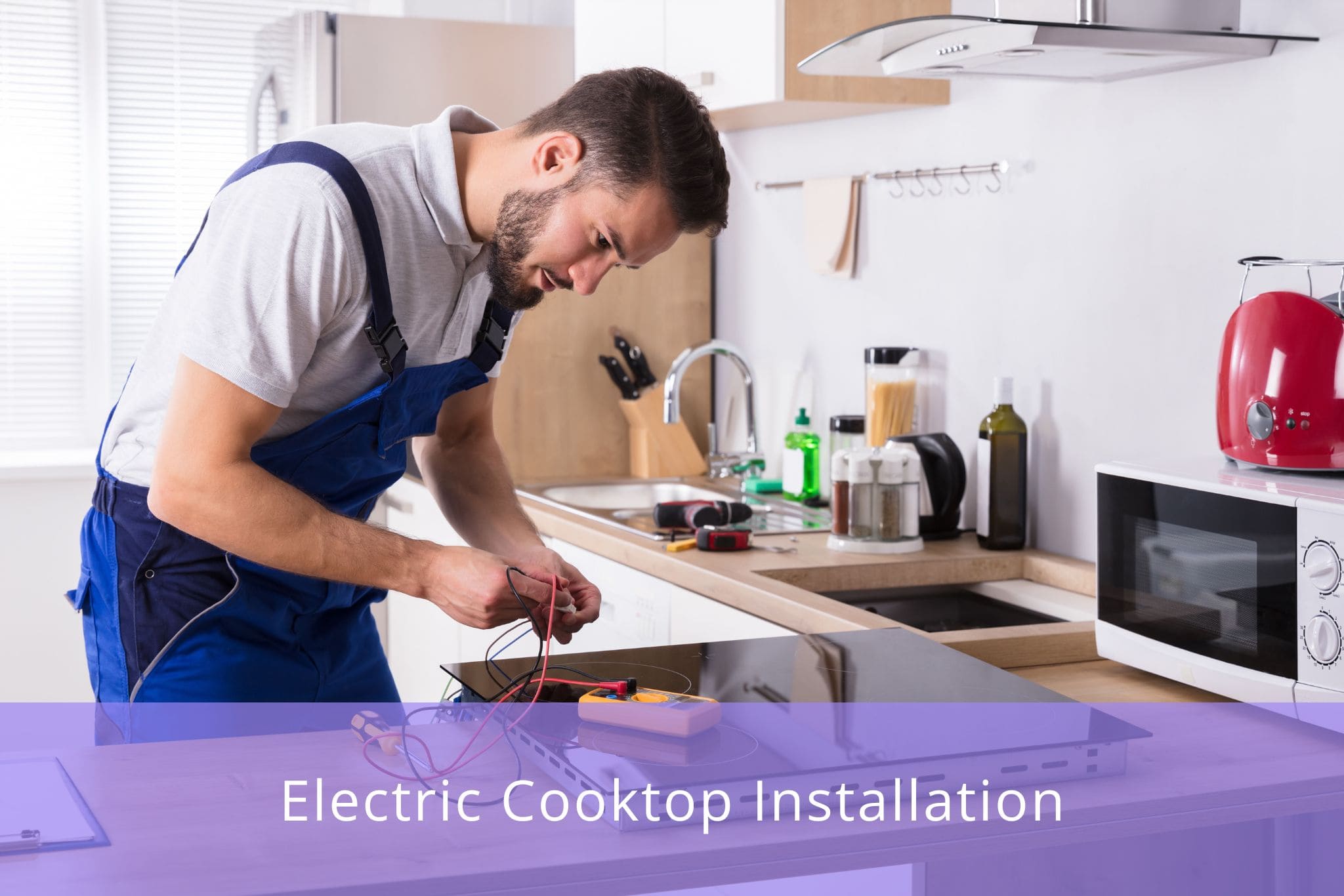
Make The Electrical Connection Correctly
De-energize the circuit at the panel and verify with a tester before opening the junction box. Review the wiring diagram for your model. Some ovens require a neutral for lights or controls; others operate line-to-line plus bonding conductor. Use a listed cable clamp where the whip or cable enters the box and ensure the clamp grips the outer jacket, not individual conductors. Replace aged or brittle connectors with temperature-rated ones sized to the conductor gauge.
Join conductors colour-to-colour per the diagram: hot-to-hot, neutral-to-neutral if required, and bond green or bare to the equipment grounding conductor and the metal box if present. Tighten set-screw lugs to the torque specified on the device or in the manual. Under-torqued lugs heat under load; over-torqued lugs damage strands. If your oven provides field-selectable rating links for 208/240 V, set them per the instructions before energizing. Close the junction box with its cover; exposed splices are unsafe and fail inspection. Label the breaker and update the panel directory.
When existing branch conductors are aluminium, use AL/CU rated connectors and antioxidant compound, and do not mix dissimilar metals in a single connector unless explicitly listed for that use. Where permitted by the appliance manual, copper pigtails can transition to existing aluminium with the correct AL/CU connector.
Pre-Energizing Safety Checks
- Verify the circuit is off using a tester, not just the breaker handle.
- Confirm the clamp secures the jacket, no copper extends beyond connector skirts, and insulation is undamaged.
- Check continuity from the oven chassis to the service panel bonding point if your meter supports it; a solid path reduces shock risk.
Electrical Sizing Reference
| Parameter | Typical Value Or Rule | Notes |
|---|---|---|
| Supply voltage | 120/240 V split-phase, 60 Hz | Some models permit 208 V; set links if provided by the manufacturer. |
| Breaker | Two-pole, sized to nameplate current | Do not oversize or undersize to chase trips. |
| Conductors | Two hots, neutral if required, and bonding conductor | Follow the wiring diagram and local code. |
| Conductor gauge | Per nameplate and distance | Example: 30 A often #10 AWG copper; confirm in the installation guide. |
| Junction box | Reachable after slide-out | Keeps splices accessible for diagnosis and service. |
Commission Heating, Verify Performance, And Keep Records
Restore power at the panel. The control should wake and may prompt for clock setting. Start with a moderate bake such as 175 °C (350 °F) and allow preheat. Expect a slight odour on first heat as protective oils burn off. Place an oven thermometer on the centre rack and verify temperature after the oven cycles several times. Many controls allow a small calibration offset if the displayed value differs from the thermometer.
Run convection if fitted and listen for a smooth, even fan tone with no scraping. Try broil briefly; the element should glow evenly. During each mode, touch nearby cabinet faces with the back of your hand—the surfaces should feel warm, not hot. If toe-kick or side panels feel very hot, re-check clearances and confirm that vent slots are not covered by trim.
Open the door slightly during a bake; the elements should respond as designed with the door switch. After high-heat operation, the cooling fan should continue briefly; this protects electronics and is expected behaviour.
Document what you installed and what you measured. Photograph the rating label, model and serial number, the junction box with conductors and connectors visible, and the cable routing with strain relief in place. Record breaker size, conductor gauge, torque values if measured, and any calibration offset. Keep the installation instructions, spare screws, and unused trim in a labelled envelope near the oven. Leave adjacent cabinet space clear so the oven can slide forward without striking stored items.
Performance Acceptance Targets
| Function | What To Observe | Target After Stabilizing | If Out Of Spec |
|---|---|---|---|
| Bake temperature | Thermometer vs displayed setpoint | ±10–15 °C (±18–27 °F) | Apply control offset; verify door seal and level. |
| Convection | Fan sound and air movement | Smooth tone; no scraping | Inspect fan guard and wiring clearance. |
| Broil | Element glow | Even glow across the element | Check terminations; verify supply voltage. |
| Cabinet surface temp | Hand-feel at adjacent faces | Warm, not hot | Re-check clearances and vent slot obstructions. |
| Cooling fan run-on | Time after a high-heat cycle | Short run-on typical | If absent, confirm wiring and settings. |
Basic Troubleshooting Guide
| Symptom | Likely Cause | Simple Check | Next Step |
|---|---|---|---|
| Breaker trips during preheat | Undersized breaker or loose lug | Confirm breaker rating; torque terminations | Match breaker to nameplate; re-make connections. |
| Uneven baking | Out-of-level chassis or blocked airflow | Level check; trim slots clear | Re-level; clear obstructions. |
| Door will not seal evenly | Twisted opening or bracket strain | Loosen frame, re-level, retighten evenly | Correct cabinet skew; avoid forcing hinges. |
| Display resets mid-cycle | Weak neutral or poor splice | Inspect junction box terminations | Re-make with rated connectors; verify neutral need. |
Ongoing Care And Airflow
A correct install stays correct with small, regular care. Vacuum dust from the lower grille and toe-kick a few times per year to keep cooling airflow unobstructed. Wipe the door gasket with mild detergent so it remains supple and seals effectively. Avoid hanging towels on the handle during baking; fabric can deflect exhaust air and trap heat at the cabinet face. Use self-clean cycles sparingly; the high temperature stresses components. For routine care, wipe spills when the interior is warm, not hot, and use cleaners the manufacturer approves to protect enamel and glass. If you notice frequent breaker trips, dimming lights when the oven starts, or unexplained controller resets, investigate the branch circuit: confirm breaker size, conductor gauge, quality of terminations, and whether the branch feeds other loads against best practice.
Final Checklists You Can Print
Before you leave the panel energized, review the three critical confirmations:
- Electrical path: dedicated two-pole breaker sized to the nameplate, correct gauge copper conductors or AL/CU terminations where allowed, secure lugs torqued to spec, junction box covered, bonding verified by continuity check.
- Mechanical fit: chassis level in two axes, face frame secured without distortion, door reveal even, gasket sealing uniformly, vent paths open.
- Functional acceptance: bake within ±10–15 °C, even broil glow, smooth convection tone, cabinet faces warm not hot, door switch and cavity light operating, cooling fan run-on after high-heat cycles.
FAQ
What breaker size is typical for a single wall oven?
Commonly 30 A. Some models use 20–40 A. Follow the installation manual and the nameplate.
What wire gauge should I use?
Match gauge to the nameplate current and run length. Example: many 30 A circuits use #10 AWG copper. Confirm in the appliance manual and local code.
Can I reuse an old junction box location?
Only if it stays reachable after the oven is slid forward and does not interfere with the rear profile. Relocate if the chassis cannot sit flush or if the cable would be crushed.
Do I need a neutral conductor?
Some ovens require a neutral for lights or controls. Others use two hots plus bonding conductor. Check the wiring diagram on the unit.
How much clearance do I need around the oven?
Follow the model-specific chart. Typical side clearance is 6–13 mm, top clearance 13–19 mm. Keep trim vent slots unobstructed.
How do I verify the cut-out before lifting the oven?
Measure width at face and back, height, and depth. Confirm parallelism within 2–3 mm. Check floor flatness within 2 mm across the width.
Why does the oven smell during the first heat?
Protective oils burn off. Run a moderate bake and ventilate the room. The odour should fade after a few cycles.
What should the cabinet surfaces feel like during operation?
Warm, not hot. If panels feel very hot, recheck clearances and confirm that vent slots are clear.
How can I quickly tell if the door seal is good?
Check the reveal for even gaps on all sides. In a dim room, do a torch test around the gasket. No light should pass.
What checks should I perform before restoring power?
Verify the circuit is de-energized with a tester. Confirm no copper is exposed beyond connector skirts. Check continuity from chassis to the bonding point if your meter supports it. Install the box cover and label the breaker.
What is a reasonable acceptance range for bake temperature?
±10–15 °C after stabilizing. If outside, verify level and door seal, then apply the control offset.
Why does the cooling fan run after I turn the oven off?
Run-on protects electronics. It should stop after a short period.
Sources
- CSA Group. C22.1, Part I. Electrical Code.
- CSA C22.2 product standards and certification markings on the appliance nameplate.
- UL and CSA listings for wire connectors, lugs, and cable clamps indicated for CU and AL/CU terminations.
- National Fire Protection Association. NFPA 70, Article 422 and related wiring methods, used for cross-reference where permitted by the authority having jurisdiction.